<B:LOOP VALUES='DATA:POSTS' VAR='POST'><B:INCLUDE DATA='POST' NAME='POST'></B:INCLUDE></B:LOOP> ~ <DATA:BLOG.TITLE></DATA:BLOG.TITLE> <DATA:BLOG.PAGETITLE></DATA:BLOG.PAGETITLE>

Chủ Nhật, 27 tháng 10, 2013

DỊCH VỤ UNBRICK CỨU BOOT, CỨU DỮ LIỆU, XÓA PASS, UNLOCK NẠP TIẾNG VIỆT, FIX IMEI


Dịch Vụ Unbrick, Cứu BOOT, ROOT, Nạp TV, UNLOCK, Xóa PASS, Cứu dữ liệu

Với đội ngũ kỹ thuật giàu kinh nghiệm, từng tiếp xúc với nhiều đời máy (LG, SAMSUNG, HTC, NOKIA,…)
Dịch vụ nhanh. Quí khách có thể đợi lấy máy ngay. Trong vòng 1-2h tùy đời máy
Dịch vụ bình thường: Quí khách để máy lại chúng tôi sẽ kiểm tra tình trạng và báo lại cho quí khách cách thức sửa chữa, nếu máy của quí khách thuộc diện không cần mở máy, chúng tôi cam kết không mở máy, Chúng tôi luôn đầu tư các kỹ thuật tiên tiến nhất để có thể hạn chế tối đa việc mở máy, hàn dây lên máy, hay thay IC FLASH.
Giá dịch vụ vui lòng gọi 0945649089 - 0916768580

Hướng dẫn phân biệt tình trạng BRICK.
BRICK: hay còn gọi mất BOOT, DIE BOOT, là tình trạng máy của quí khách hoàn toàn tối đen, không sạc, không đèn led, đèn hình, cắm vào máy tính có thể có tiếng bíp nhưng không thể kết nối nên không thể nạp lại rom.
Nguyên nhân brick: Có rất nhiều nguyên nhân dẫn đến BRICK.

  •  Up rom sai, hoặc cài một ứng dụng không phù hợp cũng có thể làm brick máy (rom cock, mod,) thường hơn 90% trường hợp brick rơi vào nguyên nhân này. Trường hợp này có thể cứu được bằng BOX, TOOL,…
  • Lỗi EMMC, BASEBAND, up sai rom làm lỗi cấu trúc khởi động của máy, hay máy có tính năng bảo mật tự khóa khởi động khi phát hiện sai cấu trúc, nếu bị lỗi này  máy vẫn có thể vào được recovery mode, fastboot, download mode nhưng không thể up rom được cái này gọi là SOFT BRICK. Có trường hợp softbrick có khả năng cứu được, có trường hợp phải thay ic flash rất tốn kém.
  • Hỏng chip IC (EMMC MCU, BASEBAND) : Gặp phải trường hợp này là do máy của quí khách bị hỏng 1 hoặc tất cả các IC trên, quí khách chỉ gặp lỗi này do đang xài bình thường, sạc qua đêm mở nguồn không lên, hoặc không thể khới động. Gặp trường hợp này quí khách chỉ còn nước thay IC mà thôi.

Một số hình ảnh khi unbrick bằng box:


Các dòng máy hỗ trợ repair boot không cần hàn dây lên main
Z01 U8800 U8800+
Z02 LG P990 P999 P993 MODEM
Z03 LG E510 E612 E720 E900 C550 C660 C660H C710H E400 E405 E435 E615 E720 GD880 GM730 GN750 GT540 KU3700 P350 P500 P690 P698 P705 P715 (F160S F160L F160K F200L F200S F200K-need 14P) all the same LG 14P JTAG Pinouts
Z04 LG E970 E960 E973 E971 E975 F180L/S/K E975W E976 E975R E975K LS970 E978 E977 E975T LGL21 L-01EZ05 LG Z-05 F260L F260S F260K P870 L-06C .all the LG 30P JTAG Pinouts
Z06 LG P880 P970 SU870 K5400 SU760 P725 SU540 all the sameLG 30P JTAG Pinouts
Z07 LG SU640 LU6200 F100L/S/K F120L/S/K
Z08 LG P930 F240L F240S F240K P930 P935 P936 all the LG 24P JTAG Pinouts

Z09 LG CU920 CU575 L705I L852I all the same LG 30P JTAG Pinouts
Z10 I9003 I7500 T939 805sc F338 I5800
Z11 E110S E220L E220S E220K
Z12 M110S M190S SC-02 P7500
Z13 S8000
Z14 D710
Z15 I535 T999 T999V I747M R530M R530U L710 I747 I547 SC-06D MSM8960
Z16 I9020 I9023 I997 I9000 I897 T959 T959V YP-G1 T759
Z17 I9100G I9108 I9108X
Z18 E120L/S/K E160S/K I717 I727 I9210 P7320 E140L/S/K SC-05 SC-03 All sanaumg 20P phones
Z19 I500 I889 I9500 N7100 E210L E210S E210K
Z20 I9220 I9228 N7000 M250L
Z21 E160L
Z22 I9100 N8010 P6200 P6810 I777 M250S/K P3100 P3110 P3113 P5100 P5110 P5113


Một số hình ảnh repair boot không cần hàn


DANH SÁCH ĐIỆN THOẠI CÓ THỂ CỨU BOOT KHÔNG THÁO MÁY
Pantech Sky:
Sky A820L
Sky A830L
Sky A830S
Sky A830K
Sky A840S
Sky A850L
Sky A850S
Sky A850K
Sky A860L
Sky A860S
Sky A860K

Samsung Galaxy:
E120L
E120S
E120K
E160L
E160S
E160K

LG Optimus:
LU6200
P920
P930
P940
P940H
SU540
KU5400
P720
E975
E970
F180L
F180S
F180K

Nếu điện thoại của quí khách vẫn không tìm thấy model máy của mình không nằm trong danh sách trên xin quí khách đừng thất vọng. Vì chúng tôi  hỗ trợ theo đời vi xử lí. Quí khách chỉ cần vào trang http://www.gsmarena.com/  hoặc các trang có hỗ trợ tra cứu thông tin sản phẩm tra model điện thoại của quí vị và cho chúng tôi biết máy của quí vị dùng con vi xử lí gì ( ví dụ: Qualcomm APQ8064 Snapdragon) và tra trong danh sách dưới đây.
  
Các đời vi xử lí hiện tại hỗ trợ:
  • Generic ARM Cores: ARM7, ARM9 (ARM920, ARM926, ARM946), ARM11, CORTEX-A8,CORTEX-A9;
  • Qualcomm QSC Family: QSC1100, QSC1110, QSC6010, QSC6020, QSC6030, QSC6055, QSC6085, QSC6240, QSC6270;
  • Qualcomm MSM Family: MSM6000, MSM6150, MSM6245, MSM6246, MSM6250, MSM6250A, MSM6260, MSM6275, MSM6280, MSM6280A, MSM6281, MSM6800A, MSM6801A, MSM6290, MSM7225, MSM7227, MSM7625, MSM7627, MSM7230, MSM8255, MSM8255T, MSM8260;
  • Qualcomm QSD Family: QSD8250, QSD8650;
  • Marvell/XScale Family: PXA270, PXA271, PXA272, PXA310, PXA312, PXA320.
  • Samsung Processors: S5P6422, S5PV310,S5PC110,S5PC210
Nếu máy của quí khách bị hỏng chip IC ổ cứng mà chưa có linh kiện thay thế chúng tôi vẫn có một số giải pháp tình thế cho máy của quí khách là dùng thẻ nhớ ngoài thay thế


Thứ Năm, 24 tháng 10, 2013

CHINA Mobile Phones Secret Codes

CHINA Mobile Phones Secret Codes

Default user code: 1122, 3344, 1234, 5678
Engineer mode: *#110*01#
Enable COM port: *#110*01# -> Device -> Set UART -> PS Config -> UART1/115200
Factory mode: *#987#
LCD contrast: *#369#
Restore factory settings: *#987*99#
Software version: *#800#
Software version: *#900#
Set default language: *#0000# Send
Set English language: *#0044# Send
Set English language (new firmware): *#001# Send

Service codes Fly:
2040(i) reset defaults: *#987*99# Send
M100 software version: ####0000#
MX200 reset defaults: *#987*99# Send
MX200 software version: *#900# Send
MP500 reset defaults: *#987*99# Send
MP500 software version: *#900# Send
SL300m reset defaults: *#987*99# Send
SL300m software version: *#900# Send
SL500m reset defaults: *#987*99# Send
SL500m software version: *#900# Send
Set language to English: *#0044#
Set language to Russian: *#0007#

Thứ Ba, 15 tháng 10, 2013

Phone LG PC Suite Version Hacker v1.0 - Install your KDZ files with LG PC Suite

Phone LG PC Suite Version Hacker v1.0 - Install your KDZ files with LG PC Suite

Quote:
IMPORTANT
Do NOT use this tool to DOWNGRADE from v20X to v10X!

You can safely UPGRADE from v10X to v20X or you can upgrade or downgrade between any two versions of v10X and v20X. (i.e. from v10F to v10H or from v20A to v20B)
Quote:
You can also use LG Mobile Support Tool together with LG PC Suite Version Hacker to install KDZ files.
You can download the tool from the link below:
http://tool.xcdn.gdms.lge.com/client...2CAppSetup.exe
Quote:
I myself upgraded from v10F to v10H, from v10H to v20A leaked version and from v20A leaked version to v20A official version using Windows XP without any problems and wihout losing any settings or applications.
Quote:
Make sure your KDZ file does not contain any spaces in the file name.
Flashing KDZ files on an LG phone is a complex task.

I've developed a helper application which can be used to flash any KDZ file on your hard disk using LG PC Suite.

WARNING: Use this application at your own risk.

Here are the steps to flash a KDZ file:

1. Download the application from: http://www.tazetaze.com/?dl_id=5 (186 KB)

2. Extract the LGKDZ.exe file from the zip file and execute it. (Minimum .NET Framework 2.0 required)

3. If you get a warning like the one below, click any button you like. (it does not affect the application)


4. Click "Click to select KDZ file" button and select your KDZ file. Make sure the file name does not contain any spaces.


5. Connect your phone to PC with the USB cable and run LG PC Suite. (tested with LG PC Suite v5.2)

6. After your phone is recognized by LG PC Suite, click the "Upgrade Check" button.


7. You will see the following messages in LGKDZ application and LG PC Suite will tell you that it found a new version. Click the "Upgrade" button and proceed with the upgrade (or downgrade if you chose a KDZ file with lower version)


8. Do not close the LGKDZ application until upgrade is completed.

Waiting for your precious feedbacks...

Note 1: You must have stock LG ROM installed on your phone for LG PC Suite to recognize your phone. With custom ROMs, this solution will not work.

HOW IT WORKS:

When you click the "Upgrade Check" button, LG PC Suite sends a query to LG servers with your IMEI number asking the lastest version of the firmware for your region.
This application captures this request, changes the latest version info to V99Z, and the location of the KDZ file to the file you selected on your hard drive.

So, LG PC Suite thinks that there is a new version, downloads this "new" version from your hard disk, thinking that it's downloading from the LG servers and then flashes the KDZ to your phone.

Translation of this post in other languages:

German Translation 1
German Translation 2

Chủ Nhật, 13 tháng 10, 2013

HWK Dead or Not Connected repair yourself

HWK Dead or Not Connected repair yourself

E-mail Print PDF
The solution for repair HWK not Connected or dead HWK for free. NO need to purchase Expensive dongles to repair your hwk.

Here is the schematic of HWK


Here is a schematic for serial programmer


Here is the prgrammer with documention and help


programmer

Download Hwk_Repair_Through_Serial_Port_com__0.rar from Mirrorcreator - Upload files to multiple file sharing sites

mirror mediafire

Hwk_Repair_Through_Serial_Port_com__0.rar

************************************************** ************
USB programmer or HWK Repair
Here is the USB programmer for HWK repair using pl2303, this circuit easily avilable on many USB to com downloading cable like Dku-5. samsung data cables etc...


Here is the Settings


Here is the usb Programmer

Download Hwk_Repair_Through_USB.rar from Mirrorcreator - Upload files to multiple file sharing sites

mirror mediafire

Hwk_Repair_Through_USB.rar
************************************************** ************************************************** ****************************
HWK Repair through UNIBOX
Just use your brain and you can also make this tool by anyunibox(Infinity Z3x Setool etc..)


************************************************** ***************
Orignal BSL programmer Schematic for HWK repair

Download bsl_0.rar from Mirrorcreator - Upload files to multiple file sharing sites

Mirror mediafire

ttp://www.mediafire.com/?6v10zxjswnapjnr
************************************************** *****************

Chủ Nhật, 6 tháng 10, 2013

LG MODEL NAME

http://filesdownload.net/forumdisplay.php?11-LG
service manual and kdz, lgflash file

KDZ Korean Phones

LGLU1400 LU1400 KDZ
LU140822_00.kdz

LGLU1600 LU1600 KDZ
LU160820_01.kdz

LGLU2100 LU2100 KDZ
LU210927_00.kdz

LGLU2300 LU2300 KDZ
LU230058_00.kdz

LGLU2700 LU2700 KDZ
LU270012_00.kdz

LGLU200S LU2700S KDZ

LU27S106_00.kdz

LGLU3000 LU3000 KDZ
LU300031_00.kdz


LGLU3100 LU3100 KDZ
LU310027_00.kdz

LGLU3700 LU3700 KDZ
LU370039_00.kdz

LGLU4300 LU4300 KDZ
LU430012_00.kdz

LGLU4500 LU4500 KDZ
LU450006_00.kdz

LGLU5400 LU5400 KDZ
LU540141_00.kdz

LGLU6200 LU6200 KDZ
LU620167_00.kdz

LGLU6300 LU6300 KDZ
LU630926_00.kdz

LGLU6500 LU6500 KDZ
LU650128_00.kdz

LGLU6800 LU6800 KDZ
LU680181_01.kdz


LGLU8300 LU8300 KDZ
LU830133_00.kdz

LGLU9000 LU9000 KDZ
LU900925_01.kdz

LGLU9100 LU9100 KDZ
LU910917_00.kdz

LGLU9400 LU9400 KDZ
LU940033_00.kdz

LGLU9400W LU9400W KDZ
LU94W017_00.kdz
LGSH100 SH100 KDZ
SW100617_00.kdz

LGSH110 SH110 KDZ
SW110617_00.kdz


LGSH130 SH130 KDZ
SW130718_00.kdz

LGSH150 SH150 KDZ
SW150714_00.kdz


LGSH150A SH150A KDZ
SW15A712_00.kdz

LGSH170 SH170 KDZ
SW170710_00.kdz

LGSH210 SH210 KDZ
SW210721_00.kdz

LGSH240 SH240 KDZ
SW240814_01.kdz

LGSH400 SH400 KDZ
SW400812_00.kdz

LGSH410 SH410 KDZ
SW410807_00.kdz

LGSH460 SH460 KDZ
SW460809_00.kdz

LGSH470 SH470 KDZ
SW470808_00.kdz

LGSH490 SH490 KDZ
SW490810_00.kdz

LGSH640 SH640 KDZ
SW640810_00.kdz

LGSH650 SH650 KDZ
SW650814_00.kdz

LGSH810 SH810 KDZ
SW810909_00.kdz

LGSH840 SH840 KDZ
SH840203_00.kdz

LGSH860 SH860 KDZ
SW860908_00.kdz

LGSH860S SH860S KDZ
SH86S906_01.kdz
LGF100L F100L KDZ
F100L29l_00.kdz

LGF100S F100S KDZ
V29i_00.kdz

LGF120K F120K KDZ
V20C_00.kdz

LGF120L F120L KDZ
F120L261_00.kdz

LGF120S F120S KDZ
V20E_00.kdz

LGF160K F160K KDZ
V20C_00.kdz

LGF160L F160L KDZ
V20c_00.kdz

LGF160S F160S KDZ
V20D_00.kdz

LGF180K F180K KDZ
F180K10K_00.kdz

LGF180L F180L KDZ
F180L10P_00.kdz

LGF180S F180S KDZ
F180S10j_00.kdz

LGF200K F200K KDZ
F200K10e_00.kdz

LGF200L F200L KDZ
F200L10e_00.kdz

LGSU100 SU100 KDZ
SU100811_00.kdz MIRROR

LGSU130 SU130 KDZ
SU130911_01.kdz MIRROR

LGSU200 SU200 KDZ
SU200910_00.kdz MIRROR

LGSU210 SU210 KDZ
SU210909_00.kdz

LGSU370 SU370 KDZ
SU370028_00.kdz MIRROR

LGSU410 SU410 KDZ
SU410907_00.kdz MIRROR

LGSU420 SU420 KDZ
SU420009_00.kdz MIRROR

LGSU430 SU430 KDZ
SU430010_00.kdz MIRROR

LGSU540 SU540 KDZ
V20C_00.kdz

LGSU550 SU550 KDZ
SU550006_00.cab MIRROR

LGSU600 SU600 KDZ
SU600813_00.kdz MIRROR

LGSU630 SU630 KDZ
SU630911_37.kdz MIRROR

LGSU660 SU660 KDZ
V30C_00.kdz

LGSU760 SU760 KDZ
V30B_00.kdz MIRROR

LGSU780 SU780 KDZ
SU780107_00.kdz MIRROR

LGSU870 SU870 KDZ
V20D_00.kdz MIRROR

LGSU880 SU880 KDZ
V10M_00.kdz MIRROR

LGSU900 SU900 KDZ
SU900913_01.kdz MIRROR

LGSU910 SU910 KDZ
SU910911_00.kdz MIRROR

LGSU920 SU920 KDZ
SU920008_01.kdz MIRROR

LGSU950 SU950 KDZ
SU950019_01.kdz MIRROR

LGSU960 SU960 KDZ
SU960909_01.kdz MIRROR
LGKU1700 KU1700 KDZ
KU170910_00.kdz

LGKU2000 KU2000 KDZ
KU200913_00.kdz

LGKU2200 KU2200 KDZ
KU220004_00.kdz

LGKU2800 KU2800 KDZ
KU280107_00.kdz

LGKU3700 KU3700 KDZ

KU370040_00.kdz

LGKU3800 KU3800 KDZ
KU380005_00.kdz

LGKU4000 KU4000 KDZ
KU400911_01.kdz

LGKU4300 KU4300 KDZ
KU430006_00.kdz

LGKU5400 KU5400 KDZ
V20D_00.kdz

LGKU5900 KU5900 KDZ
V30I_00.kdz

LGKU6000 KU6000 KDZ
KU600816_00.kdz

LGKU6300 KU6300 KDZ

KU630915_00.kdz

LGKU8800 KU8800 KDZ
V10D_00.kdz

LGKU9000 KU9000 KDZ
KU900913_01.kdz

LGKU9100 KU9100 KDZ
KU910914_00.kdz

LGKU9200 KU9200 KDZ
KU920005_02.kdz

LGKU9300 KU9300 KDZ
KU930004_01.kdz

LGKU9500 KU9500 KDZ
KU950026_00.kdz

LGKU9600 KU9600 KDZ
KU960908_00.kdz


LG Nexus 4 (E960)

LG Venice (LG730)

LG Optimus Regard (LW770)

LG Spectrum II 4G (VS930)

LG Mach (LS860)

LG Optimus G LS970

LG Optimus L9 (P760/P768/P769)

LG Motion 4G (MS770)

LG Optimus Plus (AS695) [

LG Optimus G (E970/E973)

LG Intuition (VS950)

LG Splendor (US730)

LG Escape (P870)

LG Optimus M+ (MS695)

LG Optimus Elite (LS696)

LG Optimus L5 Dual (E615/E615f)

LG Connect 4G (MS840)

LG Viper (LS840)

LG Lucid (VS840)

LG Optimus Vu (P895)

LG Optimus L3 (E405)

LG Revolution (VS910)

LG Optimus True HD LTE (P936)

LG Spectrum (VS920)

LG Esteem (MS910)

LG Optimus V (VM670)

LG Optimus C (LW690)

LG Optimus 4X HD (P880)

Optimus 3D Max (P720/P725)

LG Marquee (LG855/LS855)

LG Optimus L7 (P700/705/708)

LG G2X (P999)

LG Phoenix (P505)

LG Enlighten (VS700)

LG myTouch Q (LGC800DG)

LG Optimus L5 (E610)

LG Optimus 2 (AS680)

LG Optimus U (US670)

LG Optimus Zip (L75C)

LG Optimus L3 (E400)

LG Optimus M (MS690)

LG Thrive (P506)

LG Nitro HD (P930)

LG Axis (AS740)

LG Ignite (AS855)

LG Optimus 4G LTE (P935)

LG Optimus Q (L55C)

LG DoublePlay Flip II (C729)

LG Optimus Sol (E730)

LG Apex (US740)

LG Optimus Hub (E510)

LG Prada 3 (P940)

LG Vortex (VS660)

LG Optimus Black (P970)

LG Optimus Pro (C660)

LG Optimus Thrill 4G (P925)

LG myTouch (LGE739BK)

LG Optimus Slider (VM701)

LG Optimus 3D (P920)

LG Optimus Pad (V900/L-06C)

LG Optimus Me (P350)

LG Optimus 2X (P990/P993)

LG Optimus Chic (E720)

LG Optimus Net (P690)

LG Optimus One (P500/P504)

Thứ Ba, 1 tháng 10, 2013

OSK at winlogon (before logon) *and* on user desktop (after logon)

OSK at winlogon (before logon) *and* on user desktop (after logon)

By: Frank Rysanek of FCC prumyslove systemy s.r.o. [rysanek (AT) fccps.cz]

Intro

In embedded / industrial PC hardware, on machines with touch screen only (no keyboard), you often face a requirement to have the Windows standard "On Screen Keyboard" available all the time, both "at winlogon" (when no particular user is logged in) and after logon, i.e. on a particular user's desktop.

Credits / past references / first efforts

Everybody's obvious first guess would be to run OSK.EXE using a shortcut from the "Startup" folder in the start menu, or from HKLM/Software/Microsoft/Windows/CurrentVersion/Run. That however doesn't work quite right - it runs OSK only after a particular user logs in. If you need to use OSK to log in as a particular user in the first place, this is a dead end.
Surfing the web, you can find a handful of references that point you all vaguely in the same way: you need to run OSK as a service, and it has to be a service that's allowed to "interact with desktop". And the usual suggested way of doing it is through "gpedit.msc" (Group Policies) -> "Computer Configuration" -> "Windows Settings" -> "Scripts", double-click "Startup", "Show Files", create a batch file (say osk.bat) containing just "C:\Windows\System32\osk.exe", back to the "Start Properties" dialog, and finally "Add" the batch file... And then you also have to enable "synchronous" script startup in "Computer Configuration" -> "Administrative Templates" -> "System" -> "Scripts".
Give credit where credit is due - here's a particular reference.
Thanks a lot for that hint, it got me started. It works to the extent that indeed the OnScreen Keyboard does become available within 5-10 seconds after the WinLogon dialog appears.

Early dead ends

The one problem may be, that as soon as some user logs in, the window of OSK.EXE becomes hidden (unavailable). The instance of OSK.EXE that was launched via the system startup script runs under the "SYSTEM" user (a requirement for desktop-interactive services) and has attached to the "WinLogon desktop", which is a different desktop than the one instantiated for the newly logged in user.
So, if you want to have OSK also available for the user who's already logged in, your obvious guess would be to run OSK.EXE using a shortcut from the "Startup" folder in the start menu, or from HKLM/Software/Microsoft/Windows/CurrentVersion/Run. Guess what: it doesn't work! :-) This time the trouble is, that there is a pre-existing instance of OSK.EXE running "in the background" on the WinLogon desktop (now hidden), and a new instance for your particular desktop refuses to start up.
This can be verified by killing the pre-existing instance of OSK.EXE via the task manager. Once you kill the old one, another one starts up just fine for your logged-in desktop. So you could just insert a batch file into the Startup menu or HKLM...Run, that would first kill the old instance using taskkill, and then start a new one, which would automatically bind to the current desktop. But there's another caveat: how do you re-start the global instance running under "SYSTEM" on the WinLogon desktop, when you need to log out, in order for another user to log in again? Logout scripts are possible via gpedit.msc, but those run still under the user who's just about to log out, and a user logout is not the same as a total system shutdown. => another dead end...

NSSM to the rescue: a somewhat improved launch method of "OSK as a service"

While I was googling around for something to "run an arbitrary app as a service", I first discovered the venerable NT/W2k resource kit addon called "srvany". It's not very clever (doesn't re-start the app "running as a service" if it dies), and it's a bit cumbersome to install (cmdline command + a manual mod via regedit).
And the very next thing I discovered was NSSM - a much needed replacement for srvany. It takes a single cmdline spell to install (create an NT service and insert a link to the target app) and it keeps respawning the target app if it dies. Which is useful in two important ways: it saves a user who accidentally closes OSK at the WinLogon desktop, and it helps to mainain OSK visible after logon. How come? Read on.
Installation instructions: Download NSSM, unpack nssm.exe from the ZIP file and drop it someplace into the shell path, maybe preferably into C:\Windows\System32\ as that's where such system utils tend to live. Next, open a Windows command prompt window and type

nssm install "On Screen Keyboard" C:\Windows\System32\OSK.EXE

It should respond with
Service "On Screen Keyboard" installed successfully!

Next, go to the "services" control panel (Start -> Run -> services.msc), find "On Screen Keyboard", open its properties and enable "interaction with desktop" (needed for OSK, which is a GUI application). All you need to do next is start the service right there, or maybe reboot the system, if you want to check that it really does work automagically starting from a cold boot :-) Once you log in, obviously the instance of OSK originally launched via NSSM becomes invisible. So the first thing you probably do, without giving it much thought, is kill that stale instance of OSK.EXE. Voila, OSK becomes visible right away! Heh, wait, does this make any sense? When the (now hidden) instance of OSK dies, NSSM (the actual NT service) notices that and respawns OSK.EXE. OSK is again respawned under the "SYSTEM" user, but it does bind to the currently active desktop! :-) But... uh oh. No good. This is interesting. Both your keyboard AND the OSK work fine for the Windows command prompt window. But, the keystrokes never make it into GUI applications, such as the Notepad, or the Start menu "Run" text box. This is so sad... if it wasn't for this ugly glitch, you could really do with that single "taskkill" at logon, because at logoff, the current instance of OSK is automatically killed, and NSSM respawns it to the WinLogon desktop automagically... so very sad.
So you CAN NOT just put "taskkill /F /IM OSK.EXE" into the Startup folder or gpedit.msc logon script, and get the OSK "persistent across logon". You do need to stop the MSSN "On Screen Keyboard" super-service explicitly at logon, run an explicit OSK.EXE under the current user, and re-start the "On Screen Keyboard" service again at logoff, but only after killing OSK.EXE. You have to set up the following two scripts for user logon+logoff via gpedit.msc (-> "User Configuration" -> "Windows Settings" -> "Scripts"), which will be common to all your users:
At logon, suggested script name = osk_logon.bat :

C:\Windows\system32\sc stop "On Screen Keyboard"
C:\WINDOWS\system32\osk.exe
At logoff, suggested script name = osk_logoff.bat :

C:\WINDOWS\system32\taskkill /F /IM osk.exe
C:\Windows\system32\sc start "On Screen Keyboard"
In addition, as the "current user" instance of OSK.EXE doesn't respawn automatically, the users should have some chance to run OSK using their mouse, e.g. using a shortcut on the desktop, or in the start menu, or from a dedicated app running full screen.

Remaining unresolved issues

If you have unprivileged users (users who aren't granted admin privileges), you will have a problem stopping the service from a "logged in user" context. All your users must have admin privileges for this solution to work. If there's an easy way out of this via some selective permission settings on restricted user accounts, please let me know...
You cannot have multiple users logged in in parallel, just switching from one user session to another. The logon/logoff scripts don't get run when "switching users", the "global instance" of OSK (run as a service) wouldn't be available at WinLogon when just switching users, and your users wouldn't be able to log on (to finish the switch). Unfortunately, the start menu item "switch users" (a part of the Logoff dialog) cannot be disabled selectively. You can only disable the whole "log off" item from the Start menu and add an alternative shortcut to the "logoff" command. For the same reason, it's advisable to disable automatic fallback to the WinLogon screen (screensaver password protection), so that your users don't get locked out.
Other than that, it would be possible to add an "OSK respawn shortcut" to the desktop of every user, for the purpose of switching users - but that alone doesn't save you from the WinLogon lock-out.
If there is some way to run a script/program before AND after switching to another user session, please let me know...
Obviously none of this sorcery would be needed, if OSK itself was a proper accessibility helper, inherently persistent on the desktop and switching desktops on the fly... shouldn't be that much of a problem for the big OS authoring company, right?

SPI Flash pinout of JSPI1 on the MSI P7N SLI Platinum

SPI Flash pinout of JSPI1 on the MSI P7N SLI Platinum

http://www.fccps.cz/download/adv/frr/spi/msi_spi.html

The obvious disclaimer: the hack described in this article is not supported by the manufacturer, and may void your warranty. If you void your warranty, or just totally blow your motherboard by over-voltage or improper wiring in general, I don't accept any responsibility. You're on your own. The information is provided "as is". It may be incomplete and likely fits only a narrow subset of the hardware out there (my hardware setup is precisely specified below). The article is a result of my own detective work in chip datasheets and publically available information from third parties. None of it originates from MSI.
A friend of mine bought an MSI P7N SLI Platinum mainboard. Installed it in his PC chassis, put all the components in, installed Windows, and in good faith, installed the MSI auto-update utility. As this windows-based auto-update util kicked in, the first thing it offered was a BIOS update. And after the next reboot, the machine didn't boot. It didn't even give the usual beep code if the DIMMs were removed. Clearly the BIOS flash went awry.
Based on some past reading of someone else's notes about the blessed SPI technology, I already knew what to look for when there was no obvious PLCC32 Flash on the motherboard, neither in a socket, nor soldered onboard. I found the culprit SPI Flash chip, in my case it was an MX25L8005 by Macronix International (MXIC) (datasheet available on the manufacturer's site, link too long/dynamic). But voila, in my case I could find a neat pin header nearby, labeled JSPI1 - clearly an SPI port for "manufacturer access". The 2mm spacing is a little hard to tap (difficult to get your hands on a female connector), but better than soldering the 8pin chip or sending the board for an RMA to TW and back.
This is where the JSPI1 connector is located:

Still I was a little reluctant to start some hacking around that. Out of the three local MSI importers/distributors, I managed to get someone on the phone at just one of them. He confirmed that there's no authorized local servicing center for MSI and that any flawed MSI hardware within warranty had to be shipped back to Taiwan. Which means a prospect of having your board repaired in maybe 2 months. Rather apalling. So I took the dive, downloaded the Flash chip's datasheet, started my multimeter and got on with the probing job.
Here's the pinout of JSPI1:
           ___
     Vcc  |o o|  Vcc
10   SO   |o o|   SI   9
 7   CS#  |o o| SCLK   8
     GND  |o o|  GND  18
     n.c. |o  |
          `---'
The two sideways columns of numbers are pin references to a standard PC parallel port (Canon DSUB25 male on the cable). Yes, it is possible to build a fairly simple passive adapter cable, even without a breadboard. See the aforementioned SPI flashing webpage by Rayer for a cable schematic. You only need to add a source of +3.3V for Vcc (see below). You'll also need an SPI flashing proggie coded by my friend Rayer. For DOS, which is my favourite OS for flashing, you also need a DPMI server, e.g. CWSDPMI. Just run CWSDPMI.EXE before SPIPGM.EXE.
MSI did their homework fairly well, to the extent that you can program the 8pin SMT chip in-circuit, provided that you provide a good enough external source of 3.3V. It seems that the board, if fully alive, pulls CS# low and provides clock to the SPI flash chip, which would hamper your in-circuit flashing attemtps. But, if the board is powered off, it doesn't interfere with the flash chip's pins (the relevant outputs of the south bridge / SuperIO companion are in hi-Z state. I haven't tried flashing the board on stand-by power - it might work even without an auxiliary source of +3.3V.
Anyway it's probably good practice to provide your own source of 3.3V. If you have a stabilized PSU with this sort of output, it's only appropriate to use it. I myself have solved the problem by tapping a classic internal HDD power connector (the red line) and connected two silicon diodes (not Schottky!) in series. The model I used was a small-signal 1N4148, which turned out to be fairly feeble. A 1A model like 1N4007 would be more appropriate. Some diodes may require you to insert 3 diodes in series. You have to test+measure this with some dummy load. The point is that each diode should provide a forward voltage drop of about 0.6-0.9 V. Schottky diodes give only about 0.3V of forward voltage drop. If you connect several of them in series, this turns your 5V line into something around 3.3V. My MX chip is guaranteed to work within 2.7-3.6 V, with the absolute maximum being 4.6V, so it can probably tolerate the hack with diodes, though the diode's tend to bend a lot under load. I've noticed this in my setup. With a 560Ohm dummy load, the two diodes gave about 3.6 V left. When I attached the motherboard, the output voltage of my hacked power source was down to 3V. It seems that the motherboard has quite some consumtion, e.g. the stand-by LED is alight! :-) It's certainly not just the SPI flash that gets powered. The 1N4148 actually get quite hot on the power dissipation (voltage drop times forward current).
Consider rounding this off by a relatively beefy electrolytic cap tapped straight on your cable, as close to the connector as possible. Mine was 1200 uF @ 6.3V. This should filter the Vcc line enough for stable SPI communications and flashing.
Maybe it would actually be much easier to just tap the 3.3V line straight from your desktop PC's ATX PSU connector. Stick an unfolded office clip into the cavity around an orange wire in the 20/24pin ATX plug. Still I guess additional filtering at the cable end would be appropriate.
And this is what my cable looks like in the end:

I deliberately don't publish a full schematic - work it out yourselfs. Let this be a proof that you're up to the hack, on the soldering side of things.
Things that might go wrong / might make you wonder:
SPIPGM.EXE can detect and report a few SPI chip models known to Rayer. But even if your Flash chip is not recognized as one of the well-known models, there's a good chance that SPIPGM will actually work. It certainly doesn't object, it merely asks about the size of the flash in kB. In my case, the MX25L8005 is an 8Mb chip, which means 1 MB, which equals 1024 kB. So I entered just 1024.
It's good practice to first make a backup of the original ROM contents (SPIPGM /d ), then erase the Flash chip, then flash your desired image, then read back the contents and verify that the data got written correctly (compare the two binaries - I did this using md5sum, but some file managers can do it too). If the desired image and the dump that you read back don't match, look for the source of interference.
One possible source of interference can be the PSU. Mine was a problem, until I added the 1200uF filtering cap. I noticed the problem by touching the diodes while some SPI communications were going on - the StandBy LED went dark :-) Not anymore, once I added that filter cap.
Another problem could stem from a slow LPT port. Rayer addresses this by an additional parameter to SPIPGM, which allows you to specify an additional delay, in microseconds, to the software-based clock generating loop. So for instance to add 2 microseconds to the write command, try:
SPIPGM /p NEW.BIN /d=2
Note that the peak transfer rate is about 10 kByte/s = 100 kbit/s = 10 usec full clock cycle. I don't know the details of Rayer's implementation.
Note that if you think you do need the additional delay, you should better add the delay after *every* SPIPGM command you issue, i.e. when reading and erasing and programming and writing.
For example, a full flashing session could look like this:
SPIPGM /d ORIGINAL.BIN /d=2
SPIPGM /e /d=2
SPIPGM /p NEW.BIN /d=2
SPIPGM /d VERIFY.BIN /d=2
Note that if you're undergoing this procedure due to a failed software/inband flash of a known-good BIOS image, the ORIGINAL.BIN likely contains garbled data. It's only any good for comparison to the image you were attempting to flash, for the purpose of studying. A good tool for comparing binary images and pointing out differences at individual bytes is a Linux-based command-line proggie called "cmp".
A similar in-circuit programming cable could possibly be constructed for attachment to a universal desktop programmer, such as one of the boxes by Elnec.sk (got one in my lab) - but that programmer runs fairly fast, it could have a problem with the longer cabling, it would still need an auxiliary source of 3.3V for the motherboard etc. After all you could have grounding problems, as the programmer is not intended for in-circuit use. The software supplied by Elnec does know my SPI flash - thumbs up in that respect :-)
Overall I have mixed feelings about this flashing situation. It's a shame that the desktop mobo manufacturers don't provide BIOS flash chips in sockets (thus saving a few cents of manufacturing costs), regardless of whether there's JEDEC or LPC or SPI flash in the socket. Sending boards back home for RMA costs *their* money too, apart from the customers' and distributors' money (whose DHL rates are usually much more pricey, from the wrong end of the world). The travel back'n'forth can take weeks to months, and the vendor's RMA department will be flooded whenever the vendor's software development dept. goofs up with their firmware update util (my friend's case). Not to mention the resulting bad reputation.
I find it positive that MSI at least provided an SPI header for in-circuit programming with a dedicated simple probe. Thanks a lot, MSI :-) Please don't do away with this pin header, after reading this webpage ;-) Again, given the freight costs and the RMA overhead on part of the vendor, I still don't understand why they don't at least document the pinout, if it's so simple. The SPI basics are known to every mobo manufacturer out there, so keeping your IP confidential is a silly excuse. Maybe their argument is that anyone who's up to the flash can easily enough find out the pinout himselfs...

REPAIR BATTERY CAPACITY

http://frantisek.rysanek.sweb.cz/battery.html

Talk to your battery

On notebook batteries controlled by the BQ2092 and BQ2040 (and maybe others)

Contents

Downloads

  • Battery refurbishment programs (a small download, linux required)
    - you'll need a Linux system with i2c 2.6.4 or higher, with the appropriate modules loaded.
  • A bootable battery refurbishment CD (no hassle, a 7.5MB download)
    There are several download sites (a file this large cannot be placed at SWEB.CZ for free):
    Thanks to everyone who has provided storage space.
    The compressed .tgz archive can be opened with WinZip, yielding an .iso CDrom image. It contains a minimalistic bootable Linux based on RedHat 8, text mode (no X) with the i2c-progs packaged in, a shell script presenting a menu, some basic goodies to facilitate freestyle improvising (vim, mc, basic system environment, five unrestricted shell consoles at ALT+F2 to ALT+F6), a bit of documentation. Source code for the utils is included and the contents of the CD can of course be modified / reused (GPL applies).
    The CD boots a RedHat linux-2.4.18-14 kernel with the appropriate i2c+lm_sensors 2.7.0 modules.
    In other words, if you download this, you don't need to compile your own kernel, i2c and lm_sensors.
Either way, you'll need to solder the necessary wiring probes for the parallel port (see below). Be aware that not all parallel port chipsets support the style of abuse employed by the i2c-pport driver. A few specific desktop and server chipsets are known not to work. With the chipsets that do work, you'll need to check your BIOS SETUP - most of the parallel port chipsets are compatible with i2c-pport in the "normal" or "SPP" modes. Notebook chipsets in general seem to be quite tolerant. See the included help.txt for details.
Apart from the utils tailored specifically for the BQ2092 or the BQ2040, there's the generic "eeprom" program (taken from the lm_sensors package) that can be used for reading and writing of any 24cXX i2c EEPROM (24C01 through 24C16), not only in smart batteries but in general.
Speaking of smart batteries, the eeprom util can be used for playing with other gas gauge IC's apart from the two aforementioned models, even with undocumented ones - the only condition is that the gas gauge IC is using an external 24cXX series serial flash EEPROM. This external EEPROM never stores executable code (not even with general-purpose MCU's) - it's barely large enough to hold some callibration parameters and runtime variables that need to be non-volatile. These can be hacked.
WARNINGS:

  • Please note that the software alone will not revive your battery. The software is just a helper, intended to reset the gas gauge IC when the worn battery cells are replaced with new ones. I.e., before or while trying the software, to revive your battery for real, you still need to replace the battery cells!
  • The software and procedures presented are a bunch of hacks, not guaranteed to work for everyone or anyone.
  • The SBS standard doesn't specify a standard way to reset the gas-gauge IC upon battery refurbishment. In practise, the reset procedure is different with different chips - some chips are not documented at all (apart from compliance to the SBS spec), some have a documented way to reset the chip, with some chips the documented reset method doesn't work. The morale is: Don't use the reset utils dedicated for a particular chip with different chips! If you do, you can nuke your gas gauge chip!
  • The i2c "interface" is using the parallel port hardware in a somewhat non-standard way, potentially harmful to the hardware. Though it has never been observed so far, theoretically you can nuke your parallel port!
  • The software and procedures are provided "AS IS" - I disclaim liability for any damage to your battery, your parallel port, your health, or any other damage caused or implied by the use thereof. You have been warned.

Schematics of adapters for the i2c-pport driver

The BQ family of gas gauge chips (and probably others) feature two busses that can be tapped: the external SMBus available in the battery connector, and the internal I2C for communication with the Flash EEPROM.
The wiring is almost identical - nevertheless, for easier switch-overs during the refurbishment, I recommend that you make two distinct adapters.
The numbered connector templates have been copied from the excellent Hardware Book web site. The connectors are oriented equal to the scenario where you face the rear side of the PC and gaze at its connectors. Besides, the pin numbers are usually imprinted in the plastic bodies of the connectors.

SMBus - external port

The parallel port pins have the following meanings:
14) SDA
16) SCL
18) ground (this can really be any pin from 18 to 25)


(A photo)

Internal I2C to the EEPROM

This adapter is not quite neceesary for resetting the BQ2092.
24C0XCanon 25
418
514
616


24C0XPS2 keyb.
84
24C0XAT keyb.
85

(A photo) Note the fine enamel wires for easier wiretapping of the SMT EEPROM.

How to build a custom Linux kernel and install i2c/lm_sensors

If you downloaded the whole CD, you don't need to do this. If you decide to build from source, you'll need to go through the full kernel build&install procedure:
cd /usr/src/linux      (wherever this symlink points)
make mrproper          (careful, erases .config - make a backup first)
make symlinks
make menuconfig
make dep
make
make bzImage
make modules
make modules_install
Escpecially if you leave module versioning on, the build system generates a new magic number each time you run 'make dep', that is then used to "stamp" (decorate) all symbols in kernel modules. In effect, once you run 'make dep' with module versions on, you'll have to explicitly re-compile and re-install any external modules, e.g. i2c and lm_sensors. Otherwise, upon insmod you get error messages such as "undefined symbol function_name_335cxxt434()."
The kernel + lm_sensors configuration & build instructions are different for Linux 2.2 and for Linux 2.4. My proven-to-work testbeds are RedHat Linux 2.2.14 + i2c-2.6.4 and RedHat Linux 2.4.18 + i2c-2.7.0 + lm_sensors-2.7.0. With some of the details I don't know whether to attribute them to i2c or the kernel, therefore I list them together, the way they worked for me.
The i2c and lm_sensors packages should be available from www.lm-sensors.nu. Note: don't turn ON the original i2c drivers that come with the original kernel sources from your distro - it is strongly recommended that you download the fresh i2c package.
There are about three different ways to compile i2c and lm_sensors - the least disruptive way is perhaps the classic "tar xvzf tarball.tgz", "make" and "make install". This way the package is compiled as stand-alone modules that get installed in the correct place. You have yet to run "depmod -a", which is however typically done automatically by the Linux boot process (at least it works that way in my RedHat).
Alternatively, you can patch the kernel sources and hard-compile the drivers in - which is nevertheless completely unnecessary. The stand-alone modular installation seems safer to the kernel source tree, worked fine for me and the i2c package thus installed works without a hitch.
To be able to compile i2c/lm_sensors, you'll need the following packages installed: python, bison, byacc and flex.

Linux 2.2 + i2c-2.6.4

I recommend that you leave the parallel port driver "ON" and turn the printer driver "OFF". In `make menuconfig', this can be achieved by toggling "general setup"->"Parallel port support" ON, "general setup"->"PC-style hardware" ON and "Character devices"->"Parallel printer support" OFF. In a standard kernel, the printer driver is ON, which causes a failure when you try to load the i2c-pport module ("device in use") - sure, that's because the parallel port is occupied by the printer driver. You don't need the lmsensors application package - all you need is the bare i2c support in the kernel, i.e. the i2c tarball.
Once we have a kernel without the printer driver, and the i2c modules are installed, we can insert the modules:

modprobe i2c-core
modprobe i2c-dev
modprobe i2c-pport
Worked for me within the following environment:
RedHat 6.2 CZ with a more or less original 2.2.14 kernel and the original GCC compiler (2.91.66). All of that on a Compaq Presario 1622 notebook :)

Linux 2.4 + i2c-2.7.0

It seems that you have to turn parallel port support OFF entirely, in the Linux kernel config. You need to compile both i2c and lm_sensors.
You need to load the following modules:

modprobe i2c-core
modprobe dmi_scan
modprobe i2c-algo-bit
modprobe i2c-dev
modprobe i2c-proc
modprobe i2c-pport
Worked for me within the following environment:
RedHat 8.0 with a custom 2.4.18 kernel (the original 2.4.18-14, RedHat flavor) and the original GCC compiler (RedHat 3.2-7).
All of that built on a desktop based on VIA KT333 with an Athlon XP 1700+, but I had to actually run the software on different machines, because the VIA KT333's parallel port didn't work for i2c-pport.

Device nodes for i2c

The documentation of the i2c package further describes how to create the "device special files" /dev/i2c* using `mknod', unless you already have them. If you're familiar with mknod, you only need to know the major and minor device number. Try 'cat /proc/devices' to get the major number (and verify that the i2c driver is loaded). The minor numbers start with a zero in ascending order. You'll probably only ever need /dev/i2c0. I myself had the devices ready out of the box which has saved me the hassle with mknod.

The original BQ2092 story

Introduction - of batteries and screwdrivers

This material describes a reasonably simple way to have a nice chat over I2C with "smart" batteries of many notebook brands - which may be a necessary step in a successful battery refurbishment procedure. Is anyone outside of eastern Europe refurbishing notebook batteries, BTW? Some time ago, I've purchased a second-hand Compaq Presario 1622 - an american model, possibly imported into the Czech Republic already as a pile of trash. It only needed to have its battery refurbished - which seemed to be "no great problem". By the mechanical finish, the battery refurbishment company I've chosen has done a great job - and they've enclosed a neat measurement protocol, certifying perfect condition and capacity. Unfortunately, once inserted back into the notebook, the battery didn't work properly - the notebook would report full charge after five minutes of charging, and full discharge after five minutes of operation on batteries, following up with an immediate shutdown.
As I needed to start to work with the notebook ASAP, I went to a brand service center. "That's the battery. It'll take two days to deliver - your notebook is a U.S. model". I asked them to check the charger inside the notebook, before I pay them an outrageous sum of money for a shiny new battery, that might ultimately be no use if the charger is broken. "Allright, our technician will take a look at it tomorrow. We'll charge you some additional money for the work, and if the bettery replacement doesn't fix the problem, we'll take the battery back." And that's exactly how we did it. It was indeed the battery. No problem that it took them a fortnight to deliver the battery. I didn't even mind coming twice to pick up my notebook just because they didn't have the battery out of stock the first time around (after they'd invited me).
As this was an after-guarantee part replacement / material purchase, I got my "broken" battery back from the service center. So I went to complain about the refurbishment to the refurbishment company. No problem here - they've apologized, reported that they'd found and replaced a misbehaving cell and provided an even neater measurement protocol.
Nevertheless, even after my complaint was thus processed, the battery didn't come back to life. Unfortunately I couldn't find a "battery formatting util" on the web or from friends (as I have found out later, it wouldn't help me anyway - see the technical description below.) So I took it as a challenge and ventured a frontal screwdriver attack at the battery. When I first opened the lid, I had to nod in appreciation upon the mechanical purity of the refurbishment. The refurbishment guys did a great job even on the inside.
The battery had a reasonable voltage, precisely identical across every cell. By the voltage and the typical discharge curve, it was charged to about 70 per cent - even though the notebook was reporting 0 per cent. It was also able to generate reasonable current, without dropping the voltage significantly. Unfortunately my homebrew electronics equipment and limited time didn't allow for a more detailed exploration, such as a proper capacity measurements etc.
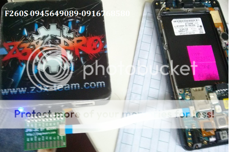
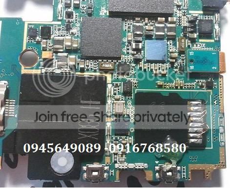
I discovered that the battery contained a tiny PCB, with two SMT IC's on it: a larger one (a DIL16 package) and a smaller one (a DIL8). I managed to read the codes: the smaller one was an AT24C02 (clearly an I2C/serial EEPROM by Atmel) and the larger one was a BQ2092. And voila - it's called a "gas gauge", manufactured by Texas Instruments (originally by Unitrode, later acquired by TI), and there's a datasheet available. Cautious optimism :)
It didn't take long to discover that I can talk to the BQ2092 using its SMBUS port. The SMBUS is electrically compatible with I2C, SMBUS commands are a subset of I2C commands. The serial flash contains pre-programmed initial values and some run-time data - so that even if the PCB with BQ2092 loses power, e.g. during a cell refurbishment procedure, the gas gauge IC still remembers the old remaining capacity. The IC can be asked via I2C to perform a reset - later on I discovered that you need to power-cycle the IC to complete the reset (unsolder/resolder the battery of cells from/to the PCB). The I2C flash is connected to a "private" I2C port of the BQ2092 that is not directly accessible at the outer battery connector. The I2C flash could be accessed on the PCB using conductors with some sorta in-circuit probes - this way the gas gauge circuit can be callibrated.
I also remembered that there was some I2C support under Linux. It turned out that most of the software in Linux is written for a myriad of internal PC peripherials, such as heatsink temperature sensors, fan RPM counters, TV and radio tuners and whatever have you. It took me a while to find the parallel port driver by Daniel Smolik. I was also lucky that I already had previous experience with #including conflicting header files in GNU C/C++ - so that I managed to wrestle the direct inclusions of kernel headers within user-space code, which is a prerequisite for using the I2C library functions (macros). And in the end finally I had a nice conversation with my battery - I've retrieved a heap of data out of it, managed to interpret most of it, and finally I've also managed to reset it.
And I was lucky - even the mere reset has woken up the battery to pretty much normal operation :) Even though perhaps it would use some callibration. No time and no equipment for that, though.
For more technical information, read on.

A brief technical description

My battery contains NiMH cells, its nominal capacity is 3800 mAh at 9.6 V (eight cells). The manufacturer is a taiwanese OEM called GLW. Besides Presario 1600, the battery also fits into a Presario 1200. There's also a newer 4,5 Ah model in the same format, and a Li-Ion battery (3.6 Ah at 14.4V ). In other words, it would seem that the built-in charger of the notebook is indeed somewhat smart. GLW manufactures batteries for many different notebook brands and models. Some time ago, I myself was speculating about the outer pinout of a Li-Ion battery in a Compaq Armada M700 that I had in my previous job - the battery is smaller and the shape is different, but the number of pins is identical (five) and so is the power supply voltage (18.5 V), and a few simple electrical measurements were showing similar results to what I have later encountered with my current NiMH battery (that is certainly older by date of manufacture). The battery is controlled (or perhaps I'd better say "monitored") by a built-in IC called BQ2092, that is communicating with the notebook via SMBus/I2C.

This image is just a poor-quality preview - you can check out the schematic in full quality in the data sheet available from Texas Instruments. You'd better download the datasheet anyway - you'll need it to interpret data read from the battery, if you decide to try that. Somewhere among the application notes on the same web site, there's a generic PCB, amusingly similar to the one I've found in my battery pack - only the current-sensing power resistor is created as a section of a winding thin copper trace, whereas in my battery there's a true discrete SMT device. Apart from the cells and the PCB, the battery pack further contains a discrete thermistor connected to the outer connector (despite the fact that the BQ2092 itself contains a temperature sensor and the value measured is available via I2C) and also a fuse, that's connected in series with the cells and is hidden somewhere among them. Another noteworthy element of the PCB are the four LED's comprising a charge indication bar graph, activated by pressing the "DISPLAY" button.
The TI pages also contain other members of the Unitrode's "gas gauge" family, such as the now deprecated BQ219 or the newer BQ2040 and more - check out the "gas gauges" product folder. The principal I2C communication and probably even the register set should be fairly similar. At the USENET forums there are several reports of the BQ2092 being quite frequent in numerous different batteries. According to the documentation, it can cope with both NiMH and Li-Ion batteries. Therefore it's reasonable to conclude that the information presented here could be useful with many different notebook brands and models.
Next, we need to solve how to connect the battery to a computer via I2C. This can be arranged using the parallel printer port - all you need is a male 25pin Canon connector (D-SUB25M), a piece of cable or thin conductors (three strands) and a few pieces of brass of whatever origin, that can serve as makeshift blade contacts against the female battery connector. And of course you need a soldering iron and a piece of tin and resin.
The battery's got five pins - see the picture below. The list below the picture shows their meanings:

  1. +V(batt) = positive battery terminal. This pin goes straight to the positive terminal of the first cell.
  2. SMBC aka SCL (SM Bus Clock, Serial CLock)
  3. SMBD aka SDA (SM Bus Data, Serial DAta)
  4. thermistor(+). Its second leg is connected to ground (pin #5).
  5. Ground = negative battery terminal. Well, almost - between this pin and the negative terminal of the last cell, there's the current-sensing resistor (0.05 Ohms). I.e., the outer pin #5 is connected to the PCB, which is connected straight to the last cell.
This is the pinout at the parallel port (for the i2c-pport driver by Daniel Smolik that's a part of the Linux-based I2C package):
14) SDA
16) SCL
18) ground (in fact this can be any pin between 18 and 25 - all of them are GND)
Tu sum up, the battery connector can be connected to the parallel port in the following way:
BatteryCanon 25
216
314
518

Check the chapter on Kernel compilation on how to roll your own kernel and install the i2c/lm_sensors modules. Last but not least, we need to talk to the battery. My preferred way to write a simple proggie in C. I tried C++ but the compiler kept repulsing the kernel headers - that need to be directly included and collide with things in the standard C++ library, e.g. in the header file. Bare C was easier to tame. Here are the code snippets I could come up with. There are two very basic programs that should allow you to read the contents of the BQ2092's registers and to reset the IC. For obscure reasons, you have to compile them with some optimization turned on - 
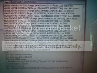
e.g., try `cc -O2 read_batt.c -o read_batt'. The output of read_batt.c looks like this: the fresh original battery and the refurbished battery before the reset.
The battery (BQ2092) provides a heap of data: instantaneous voltage and current, temperature, what the IC thinks is the remaining effective capacity, current charge level (per cent), voltage tresholds for full charge and full discharge, including an early warning treshold, reporting that the battery is running our of gas. Most values are coded as a 16bit word, expressing the value measuder in "milli"units - i.e., voltage in milliVolts or temperature in milliKelvins. Some values are slightly more cryptic: e.g., the low voltage tresholds are encoded as a binary complement to the 16bit integer in milliVolts. Some values IMO don't obey the documentation. The BQ2092 also contains many adressable registers that positively contain some data but are not mentioned in the documentation. For a full reference of the meanings of the individual register contents, check out the data sheet.
The documentation is also quite brief regarding the reset of the IC - which you can only find out once you actually attempt to reset it. The first surprise comes when the BQ2092 doesn't even finish the i2c transaction whereby it has obtained the RESET command - so that the Linux i2c driver reports failure when sending the RESET command. Nevertheless, by all other symptoms the reset is performed - or, more precisely, the battery reverts into a mysterious undocumented state, where the bar graph LED's seem to indicate some debugging information and the pattern shown can be affected by pressing the "DISPLAY" button. In this state the IC doesn't communicate via I2C. Only after a brief power-cycle (unsolder and reconnect one of the wires going to the cells) does the reset operation finish. During the first charge/discharge cycle the notebook misreports charge percentage - the gas gauge should get back to normal operation after the first cycle. The BQ2092 counts up and down how many mAh have entered and left the battery between the upper and lower voltage treshold. I recommend that you reset the battery when it's fully discharged - so that the gas gauge behaves somewhat normally even during the first charge cycle. Otherwise it doesn't really matter at what actual charge level you reset the battery - except for the charge level figures reported during the first cycle, this choice doesn't have any influence.

Further observations, side notes and rants

Besides the linux I2C, I know of a Slovak freeware util for Windows, available from somewhere at the Czech "hardware server", that can reportedly do a number of interesting generic things over I2C: write and read operations, including macros consisting of multiple atomic actions etc. A battery data listing and reset might as well be a piece of cake. Unfortunately I don't have the time to try it and I don't know what pinout it expects at the parallel port. Not much use for people who don't speak Slovak, anyway.
Quite probably there's also a Delphi component for I2C. Besides the primitive adapter wiring presented above, there are several more complex active I2C-to-PC interface schematics available on the 'Net, both for serial and parallel ports. During our battery experiments, occasionally we need to completely discharge the battery. Unless we have a stand-alone discharger device available (even an improvised quick hack), we need to leave the complete discharge up to the notebook. And this is where we have a problem with the more intelligent operating systems such as Windows or Linux, that set the notebook asleep well before the battery is completely empty - probably when the gas gauge reports zero per cent, or perhaps when it signals the "early warning", which is usually somewhat later. We need to discharge the battery to the very bottom - to the point where the BQ2092 detects the "hard" low treshold and invokes via I2C a complete shutdown of the notebook, to protect the battery from damage caused by over-discharge. This can be achieved by booting the notebook into legacy DOS - it's also appropriate to mute the PC speaker (using the soundcard's mixer), lest it bother us with loud passionate beeps announcing its imminent death.
I suspect that at least with some notebook models the cooperation between the fuel gauge IC, the notebook's APM BIOS and the operating system is not quite optimum. For instance, the battery pack contains a discrete thermistor accessible at the outer connector, although the gas gauge IC itself contains a temperature sensor with digital output in milliKelvins - that's a bit surprising (in fact, GLW has disobeyed the BQ2092's data sheet from Unitrode/IT in other details, too). Perhaps this is a sign of the manufacturers' inclination towards better safety - remember the trouble with some batteries auto-incinerating when in use? But that's not a real problem. What's worse is the way how the notebooks deals with the battery - which is also a fault on part of the user, after all. Both the batteries, the new one and the refurbished one, are complaining that they're not being fully discharged - thus, the remaining capacity cannot be properly derived. The charge level (percentage) and the actual battery capacity in mAh are derived from the milliAmps flowing through, being integrated over the time it takes between full charge and full discharge - more or less (there are some magical corrections in the formula).
In particular, the BQ2092 signals this "incomplete charge cycles" condition with a particular alarm bit in a certain status register - for a complete interpretation, see the data sheet. Perhaps the APM BIOS stops the discharge (by shutting down the notebook) simply based on instantaneous voltage well before the full discharge condition is reached - even in pure DOS. With respect to proper functioning of the "gas gauge", utilization of the battery and the memory effect (however disputable it is), the charging and discharging should only stop when the BQ2092 itself finds that the voltage has reached the respective treshold - of which it informs by the status bits in the respective registers, as well as by sending "broadcasts" via the I2C link to a well-known smart charger I2C address (assuming the role of an I2C bus master for the moment, even though normally the smart battery gas gauge is a slave). Obviously if the user doesn't take proper care to fully discharge the battery now and then, we can't blame the manufacturer of the gas gauge, the battery, the notebook or the operating system. In that case, it's not quite surprising if the batteries behave after sometime in such a way that the notebook shuts down hard when the gas gauge still shows over 50 per cent. Which has been observed with a rather expensive notebook model we had in my job, with many different pieces used throughout the company, with Li-Ion batteries. Well it's not all that understandable and apologizeable - it seems that the gas gauge shuts down the notebook upon reaching the overdischarge treshold, but doesn't update the "remaining capacity" register, which it certainly should under these circumstances.
Unfortunately, at that time I didn't have and I still don't have the equipment and time to do something about these mystical issues - measure them, analyze them, debug them etc. Specifically I'd have a problem debugging the I2C communications between the battery and the notebook with just my bare hands and some very basic homebrew electronics equipment.
The BQ2092 also mentions that, in order to achieve maximum precision, it is possible to fine-tune (callibrate) the initial values stored in the serial flash. The BQ2092 has several programmable parameters, such as the gain and DC error of the voltage and current sensors, that can be used to cancel in the digital domain the real-world deficiencies of the IC's inputs and of the external devices (such as resistor tolerances). The contents of the initialization data stored in the flash are again described in the BQ2092's documentation. When refurbishing a battery, it probably doesn't make much sense to spend too much time toying with these values - to check the basic functionality, it is probably sufficient to compare the voltage and current reported by the IC with data measured externally using your favourite multimeter.
Moreover, the flash is not directly accessible via the external SMBus (I2C) port of the battery pack - it's not on that bus. The BQ2092 features a separate I2C port just for the serial flash, that is not connected to the outer connector. The IC takes over some of the data directly into its registers accessible from outside, but most registers are read-only anyway under normal circumstances (although maybe not quite, see the documentation regarding the reset command) and it's not clear what result we'd achieve by an explicit modification of the BQ2092's parameters at runtime. To sum up, if we decided to fine-tune the callibration parameters a bit, we'd have to connect to the flash in-circuit - attach probes to SDA and SCL and also provide power to the serial flash IC, as the BQ2092 only powers the flash for an instant when it talks to it (otherwise it doesn't feed it). Once we'd be done with the callibration, we'd have to reset the gas gauge, so that the changes would take effect.
Why do we have to connect the battery via a parallel port? Simply because I haven't seen a hint of documentation on how the battery I2C bus is accessible internally from the operating system of the host notebook. I'd almost say that the I2C is terminated at the smart charger build into the notebook (the smart charger being controlled by a dedicated MCU). I seem to recall a note somewhere in the USENET news, saying that with some notebooks the battery I2C is terminated at the same MCU that controls the keyboard - and that this is the way how the APM BIOS communicates with the battery. Especially, I don't know how I could possibly talk to that internal I2C port - there's no public documentation and the i2c and LM-sensors packages don't contain any relevant drivers.

More on the BQ2040

The BQ2040 is another member of the Benchmarq/Unitrode/TI family of gas gauge IC's compliant with the SBS spec. As such, it has a nice datasheet, describing all the SMBus commands as well as the memory map of the external 24C01 serial Flash EEPROM. Just like the BQ2092, the BQ2040 also has a documented (but different) reset procedure, again dependent on a write-protect lock. Nevertheless, with the BQ2040 the documented reset doesn't seem to work. Not even after the write-protect lock is properly removed, which already requires you to wiretap the external 24c01.
There seems to be a workable workaround, consisting in rewriting the "actual capacity" value in the external 24c01 Flash EEPROM - a single word value (16 bits) holding the last learned capacity in mAh.
Please note that the BQ chips use a "private" i2c bus to talk to the 24c01. This private bus is not accessible via the external SMBus pins available at the battery pack's outside connector. This implies that you'll need to wiretap the 24c01 directly, with a soldering iron (or using some sorta in-circuit probe for the 8PIN SMT package, if such a thing exists).
To save power, the BQ chips only power up the external 24c01 for a second when they need to talk to it (read it or write it). At the same time, we don't want the BQ chip to notice that we've hacked the EEPROM, and we don't want it to accidentally intervene in the process, and we don't want it to ignore our new "actual capacity" value. Therefore, we prefer to power down the BQ chip while we're tampering with the 24c01 EEPROM. Which means that we definitely need to provide power to the 24c01 externally.
Fortunately, the BQ chip won't sink our external power => we don't need to cut its EEPROM power trace on the PCB.
The external +5V power line can be tapped from the Ucc pin of your PC's AT or PS/2 keyboard connector.
To sum up, the whole reset workaround procedure should look like this:

  1. Start Linux with i2c-pport and the other modules.
  2. Check the "actual capacity" value via the external SMBus connector of your battery and the read_batt util. Disconnect the SMBus probe from your PC after that.
  3. Disconnect the gas gauge PCB from the cells in the pack (perhaps replacing the cells at the same time).
  4. Attach the parallel port I2c probe to the 24c01.
  5. Attach the probe to your parallel port.
  6. Tamper the 24c01 - either using a dedicated util writing the right memory places, or using the generic eeprom read/write util and a hexa editor to edit the EEPROM image (e.g., the one in Midnight Commander - called using F3 F4).
  7. Disconnect the probe from the PC and unsolder it from the 24c01.
  8. Reconnect the battery cells to the gas gauge PCB.
  9. Check the "actual capacity" value via the external SMBus connector and the read_batt util. You should see a change.
  10. Run the battery through two or three full charge cycles in the notebook.

References

Home

Biểu mẫu liên hệ

Tên

Email *

Thông báo *